CONCEPTUAL DESIGN

CONCEPTUAL DESIGN

FRONT END ENGINEERING & DESIGN (FEED)

FRONT END ENGINEERING & DESIGN (FEED)

DETAILED DESIGN AND ENGINEERING

DETAILED DESIGN AND ENGINEERING

PMC ACTIVITIES AND COMMISSIONING

PMC ACTIVITIES AND COMMISSIONING

Latest Posts

Sunday 16 May 2021

Cooling Tower Working and Types

Competence Engineering
Cooling towers are a special kind of heat exchanger devices where air and hot water are brought into direct contact with each other in order for the evaporative cooling to take place and the temperature of the water to drop due to it. During evaporative cooling process the air has to be unsaturated so that it can store the evaporated water vapors and for the water to change its phase from liquid to gas, latent energy is required which the water absorbs from the surrounding.

Cooling Tower Working and Types


Working of a cooling tower

The working principle of a cooling tower is evaporative cooling.

The hot water is input in the equipment from the top of the cooling tower. The hot water is flows through a pipe and is made to pass through spray nozzles. The water flows in the tower as droplets. The advantage of doing this is that the surface area of contact of air water increases. The water falls down due to the influence of gravity.

The air is input in the equipment through the bottom of the cooling tower.

The water falls on the fill material. The fill materials are the zone where the intimate contact of air and hot water occurs. The fill materials are also sometimes called packings or baffles. The purpose of the fill material is to increase the effective surface area which is responsible for heat transfer.

After the hot water and air come in contact, evaporative cooling takes place which results in decrease in temperature of the water and increase in temperature of the air.

The cooled water is collected from the bottom of the cooling tower and the warm air rises and moves out from the top of the cooling tower.

Types of cooling towers

Air Draft cooling towers are classified as Atmospheric towers, Natural draft towers and Mechanical draft towers. The Mechanical draft towers are further classified into Forced draft type and Induced draft type.

Atmospheric Cooling Towers

This is the simplest type of cooling tower. It consists of a rectangular chamber which has louvered walls on the opposite end. The louvers are devices which act as barrier for splash out and sunlight, also the louvers give a direction to the flowing wind. The atmospheric air enters the cooling tower depending on the speed of the wind guided by the louvers. The tower is filled with fill material on which contact of air and water takes place. They are cheap but inefficient because the performance is largely driven by wind velocity and direction.

Natural Draft Cooling Towers

A natural draft tower is also called hyperbolic tower because it is a large concrete structure of hyperbolic shape. The tower is called so because the movement of air happens naturally inside the tower. The tower consists of a spray mechanism beneath which alternative layers of battens are stacked along with the packing material.

The air enters from the bottom and the water gets splashed when it touches battens and forms the shape of droplets. These droplets result in a good heat transfer area. The rise in temperature of the air and humidity reduces its density due to which it becomes relatively more buoyant and rises naturally. Drift eliminators are placed in the tower to catch the liquid droplets which may be entrained with the air.

Forced Draft Cooling Towers

Forced draft towers are a type of mechanical draft towers because they use fans to move air inside the cooling tower. Forced draft towers use fans at the bottom of the tower in order to push the air inside the cooling tower. The forced mechanism makes it relatively more efficient than a natural draft tower. If the fans are big enough then it may cause the motion of the air to become non-uniform while it passes through the fill material. The biggest disadvantage of forced draft tower is that it may pick up the exit air from outside and push it back inside the cooling tower. This re-circulation reduces the efficiency of the tower because the saturation level of inlet air increases.

Induced Draft Cooling Towers

Induced draft towers are designed to eliminate the re-circulation effect which happens in forced draft towers. The fans in induced draft towers are placed at the top of the cooling tower. The space for air inlet is made at the bottom of the tower. When the fan operates, suction is created at the bottom of the tower due to which the flow of air is induced.

In the counter flow mechanism of the process, the power required to move air will be high because the air entry to the packing will face the maximum resistance due to the liquid exiting the packing. Induced draft towers can be operated in concurrent flow, counter current flow and cross flow.

Steam Trap Working and Types

Competence Engineering

Steam Trap Working Principles

Steam Trap Working and Types

Energy is getting more important day by day. According to the diminishing of energy sources all the industry sectors searching for alternative sources for increasing the productivity.

In this case steam which is one of the energy carrier is also getting more important. Trapping of steam and using more heat of steam is up to choosing right steam traps. Although steam traps look simple and small their obligation is very complex. Saving more energy is related to the right chosen steam trap type and sizes. Working principles should be known well for choosing the right steam trap for the process.

Purpose of Steam Traps

The aim of a steam trap is discharging the condensate from the steam pipe line while trapping the steam. Steam use its potential heat during the applications and by the radiation heat loses on pipelines, steam turns to condensate. In case this condensate not discharged from the pipeline, it causes cavitation and water hammer beside reducing the quality of the steam.

An ideal steam trap should have the ability of air venting together with discharging the condensate. There is no “Universal Type Steam Trap” that has no disadvantages according to the application conditions. All the steam trap types have different working principles that has advantage and disadvantages. In general there is always a best trapping solutions for all kind of steam applications with its alternative. This solution depends on the temperature, pressure and amount of the condensate.

In principle steam traps have to do the followings;
  • Discharging the condensate from the pipeline
  • Trapping the steam
  • Discharging the air and gas

Types of Steam Traps

Mechanical Steam Traps

Most important characteristic of the mechanical steam traps is that they operate according to the difference of the density of steam and condensate which allows the condensate to flow.

The weight of the float, acting through the lever, keeps the valve closed when the trap is empty. As the condensate enters the trap, it raises the float and opens the valve overcoming the pressure acting on it. If no more condensate load is steady the float sets to produce a continues discharge. The condensate level in body is always above the valve creating perfect water seal the closed float trap is able to discharge the air through thermostatic air venting unit installed inside the body.

Thermostatic Steam Traps

Typical characteristics of thermostatic steam traps is to operate according to the difference in temperature of steam and condensate. As the condensate cool, the liquid condenses lowers the internal pressure of the membrane. The resultant pressure differential will favor the external pressure acting on the membrane to retract and open the orifice, permitting the condensate discharge.

Thermodynamic Steam Traps

Thermodynamic steam traps operate periodically according to the difference in dynamic pressure of steam and condensate and discharge the condensate at the same temperature of the steam. Steam entering the trap expands suddenly as it reaches the backside of the disc. The resulting high flow velocity causes a decrease in pressure under the disk. Steam above the disc gets high pressure force and this pressure balance forces the disc onto the seat to close the orifice in other words to trap the steam.

When condensate appears at the trap inlet under and above the disc the pressure force above the disc disappears and allows the condensate discharge.

Types of Centrifugal Compressor

Competence Engineering

Different Types of Centrifugal Compressor

Centrifugal Compressor

There are different types of centrifugal compressor designed for specific purposes based on the desired applications. The most popular ones are single-stage and multi-stage centrifugal compressor. Below, we’ll explain all about these compressors. It’s good to know that they follow the same principle, but they are different in their construction and how they get the job done.

Single Stage Compressor

Single-stage compressors are among the popular types of centrifugal compressors available on the market. This type has a single impeller for directing the air or other gases for its specific purpose. The single-stage compressor also contains a diffuser and connected guide vanes. IT can provide up to a three to one compression ratio because of its impeller peripheral speed as well as blade geometry. Plus, these types contain flow capacities ranging from 1000 cfm to 300 thousand cfm.

This centrifugal compressor type has different designs including overhung single-stage compressor and integrally geared single-stage compressors.

Overhung Single Stage Centrifugal Compressor

One of the most useful types of centrifugal compressors for low pressure and high volume application is the overhung single-stage compressor. The impeller in this type is placed at the non-drive side of the shaft. They have higher efficiency and a wider range of operation due to their axial flow suction nozzle. The gas flow that this compressor can handle is up to 60,000 m³/hr and up to a 3.5 pressure ratio.

Integrally Geared Single Stage Centrifugal Compressor

This type, as the name suggests, contains a single-stage compressor but has overhung semi-open impeller. The high-speed shaft of the gearbox hosts the impeller. A maximum of 300 thousand m³/hr is the amount of gas flow that this compressor type can handle. And the pressure ratio that it supports is up to 3.5. It can also achieve a discharge pressure of up to 50 bar.

Multi-Stage Compressor

Multi-stage compressors are among different types of centrifugal compressors. As the name suggests, this compressor has been designed to pass the gas through multiple stages for diverse purposes. Multi-stage compressors are used when a single-stage compressor can’t keep up with the desired pressure requirements. This is because a single-stage compressor, as mentioned above, has only one impeller.

Unlike this centrifugal compressor type, multi-stage compressors contain several impellers on the rotor. Each impeller diffuser leaves the discharge to enter the next impeller. Multi-stage compressors have different types including multi-stage centrifugal compressor with horizontally split casing, multi-stage centrifugal compressor with vertically split casing, multi-stage centrifugal compressor with bell casing, pipeline multi-stage compressors, and integrally geared multi-stage compressors.

Multi-Stage Centrifugal Compressor with Horizontally Split Casing

Among different types of centrifugal compressors, this one is popular as well. These compressors are mainly used for applications with lesser than 60 bars of gas operating pressure. Horizontally split casing compressors contains two halves of a cylindrical case. Their centerline keeps them connected by bolting.

This compressor type is not suitable for very high pressure due to the sealing and bolting limitations at the split. Almost all the piping connections of this compressor type has been placed at the lower half of the compressor. But that is not the case for the main process in and out connection since it is placed at the upper half of the system (although some designs might differ, in most cases, it is placed at the upper half.)

Multi-Stage Centrifugal Compressor with Vertically Split Casing

This centrifugal compressor with vertically split casing also looks like a cylinder and is also called a barrel. Unlike horizontally split casing compressors, a multi-stage centrifugal compressor with vertically split casing is among the types of centrifugal compressors that are perfect for applications with higher pressures. These compressors have one-piece construction and also seals at all ends of the barrel and are perfect for high pressures up to 680 bars.

Multi-Stage Centrifugal Compressor with Bell Casing

A multi-stage centrifugal compressor with bell casing is also on the list of different types of centrifugal compressors. They are named after the shape of their case that looks like a bell. This case uses shear rings for closing instead of using bolts. They are suitable for high-pressures.

Pipeline Multi-Stage Compressors

Pipeline compressors, just like the precious centrifugal compressor type have bell-shaped casings but contain a single vertical end cover. Their delivery nozzles and side suction are placed opposite of each other which make the design suitable for installation on gas pipelines. These compressor types can handle pressure up to 100 bars and are mainly suitable for natural gas transportation and similar purposes.

Integrally Geared Multi-Stage Compressors

The last item on our list is the multi-stage compressor that is integrally geared. They are used for high pressure and low flow or low pressure and high flow. Each pinion-shaft in these compressors can host up to two impellers. They have high efficiency due to their ability to inter-cool compression stages as well as their optimal impeller speed.

Gas Turbine : Overview of Types

Competence Engineering

Gas Turbine Working Principle

Gas Turbine : Overview of Types

Any gas turbine operates with intake, compression, expansion, and exhaust cycle. As a fundamental of the gas turbine working principle, in each gas turbine type, the compressor first compresses the air and this air is then driven through the combustion engine. Fuel is continuously burned for high-temperature and high-pressure gas processing. What a gas turbine is doing is expanding the gas generated by the combustor into the turbine and thus generating the rotary energy that is used by the compressor on the preceding stage. There is an output shaft for the remaining energy.

Gas Turbine Applications

Regarding gas turbine applications, these turbines are one of the most popular technologies for the generation of electricity today. Their power generation could also be utilized in chemical plants and refineries. They have significantly contributed to cleaner power generation in recent years. The production of new and advanced technologies would allow better use of gas turbines across multiple power sectors, from electricity production to transport and aviation, thereby improving the efficiency of all these industries.

Apart from electricity production in power and chemical plants, these turbomachines are also the backbone of today’s aviation and aircraft propulsion. Different types of gas turbines are used in aircrafts from small passenger ones such as the beautiful Hawker 400, formerly known as the MU-300, to the magnificent A380. They are also used in cargo airplanes from small to large such as Airbus Beluga. Military aircrafts are also propelled by jet engines.

Types of Gas Turbine

Here, we introduce the four major types of gas turbine engines. Do pay attention that such variety of gas turbine design is only present in aircraft gas turbines. For gas turbines used in power plants, the configuration is rather similar to turbojet engines to be discussed below.

Turbojet Engines

The first gas turbine type was turbojet engines. Although they look entirely different from reciprocal engines, they operate on the same principle: intake, compression, power and exhaust. In this type of engine, air is moved at a high speed to the fuel inlet and ignitor of the combustion chamber. The turbine induces accelerated exhaust gases by expanding air.

Turboprop Engines

The second gas turbine type is a turboprop engine. It is a turbojet engine that is connected via a gear system to a propeller. The working process of such a gas turbine type is as follows:
  • The turbojet spins a shaft linked to a transmission gearbox
  • A transmission box slows down the spinning process and the slowest moving gear is attached to the transmission mechanism.
  • The air propeller rotates and generates thrust

Turbofan Engines

The world’s best turbojets and turboprops is paired with turbofan engines. Turbofan engines can be connected to the front of a turbojet engine with a duct fan. The fan then creates an extra push, helps the engine to cool and reduces the engine noise output.

Turboshaft Engines

The fourth gas turbine type is turboshaft engines that are used mainly on helicopters. The biggest difference is that turboshaft engines use the bulk of their power to spin turbines instead of driving them out from the rear of the vehicle. Turboshaft engines are a turbojet motor with a large shaft connected to the back of it.

Steam Turbine Working and Types

Competence Engineering

What is Steam Turbine?

Steam Turbine Working and Types

Steam turbine comes under the classification of a mechanical machine that isolates thermal energy form the forced steam and converts this into mechanical energy. As the turbine produces rotatory motion, it is most appropriate for the operation of electrical generators. The name itself indicates the device is driven by steam and when the vaporous stream flows across the turbine’s blades, then the steam cools and then expands thus delivering almost the energy that it has and this is the continual process.

Working of Steam Turbines

As the name suggests, steam is required for the running of a steam turbine. This steam is produced by boiling water using a heat source which could be nuclear, gas or coal. This steam is then admitted towards the blades of the shaft. The blades of the turbine is in the shape of an airfoil. This shape aids in the rotation of the turbine as it provides a lift force. The turbine has a set of alternating fixed nozzle and blade arrangement. The nozzle is stationary and its area decreases from one side to the other, thereby increasing the velocity of steam flowing through it. This helps in increasing the speed of the blades as well. The turbine is connected to a generator which has a magnet that is wound by copper coils. The rotation of the magnet produces a strong magnetic field and this magnetic field causes the flow of electrons and thus electricity is generated.

Types of Steam Turbines

Steam turbines may be classified into different categories depending on their construction, working pressures, size and many other elements. But there are two basic types of steam turbines which are called impulse and reaction turbines. There are other types of steam turbines that are actually derivatives of these two main types.

1. Impulse Turbine

In this type of turbine, the superheated steam is projected at high velocity from fixed nozzles in the casing. When the steam strikes the blades (sometimes called buckets), it causes the turbine shaft to rotate. The high pressure and intermediate pressure stages of a steam turbine are usually impulse turbines. The entire pressure drops of steam take place in stationary nozzles only. Though the theoretical impulse blades have zero pressure drop in the moving blades, practically, for the flow to take place across the moving blades, there must be a small pressure drop across the moving blades also.

In impulse turbines, the steam expands through the nozzle, where most of the pressure potential energy is converted to kinetic energy. The high-velocity steam from fixed nozzles impacts the blades changes its direction, which in turn applies a force. The resulting impulse drives the blades forward, causing the rotor to turn. The main feature of these turbines is that the pressure drop per single stage can be quite large, allowing for large blades and a smaller number of stages. Except for low-power applications, turbine blades are arranged in multiple stages in series, called compounding, which greatly improves efficiency at low speeds.

2. Reaction Turbine

In this type of steam turbine, the steam passes from fixed blades of the stator through the shaped rotor blades nozzles causing a reaction and rotating the turbine shaft. The low pressure stage of a steam turbine is usually a reaction type turbine. This steam having already expanded through the high and intermediate stages of the turbine is now of low pressure and temperature, ideally suited to a reaction turbine.

In reaction turbines, the steam expands through the fixed nozzle, where the pressure potential energy is converted to kinetic energy. The high-velocity steam from fixed nozzles impacts the blades (nozzles), changes their direction, and undergoes further expansion. The change in its direction and the steam acceleration applies a force. The resulting impulse drives the blades forward, causing the rotor to turn. There is no net change in steam velocity across the stage but with a decrease in both pressure and temperature, reflecting the work performed in the driving of the rotor. In this type of turbine, the pressure drops take place in a number of stages, because the pressure drop in a single stage is limited.

The main feature of this type of turbine is that in contrast to the impulse turbine, the pressure drop per stage is lower, so the blades become smaller and the number of stages increases. On the other hand, reaction turbines are usually more efficient, i.e. they have higher “isentropic turbine efficiency”. The reaction turbine was invented by Sir Charles Parsons and is known as the Parsons turbine.

In the case of steam turbines, such as would be used for electricity generation, a reaction turbine would require approximately double the number of blade rows as an impulse turbine, for the same degree of thermal energy conversion. Whilst this makes the reaction turbine much longer and heavier, the overall efficiency of a reaction turbine is slightly higher than the equivalent impulse turbine for the same thermal energy conversion.

Monday 3 May 2021

Water Tube Boiler | Operation and Types of Water Tube Boiler

Competence Engineering
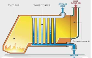
A water tube boiler is such kind of boiler where the water is heated inside tubes and the hot gasses surround them. This is the basic definition of water tube boiler. Actually this boiler is just opposite of fire tube boiler where hot gasses are passed through tubes which are surrounded by water.

Water Tube Boiler
Water Tube Boiler

Advantages of Water Tube Boiler

There are many advantages of water tube boiler due to which these types of boiler are essentially used in large thermal power station.
  • Larger heating surface can be achieved by using more numbers of water tubes.
  • Due to convectional flow, movement of water is much faster than that of fire tube boiler, hence rate of heat transfer is high which results into higher efficiency.
  • Very high pressure in order of 140 kg/cm2 can be obtained smoothly.

Working Principle of Water Tube Boiler

The working principle of water tube boiler is very interesting and simple.

Let us draw a very basic diagram of water tube boiler. It consists of mainly two drums, one is upper drum called steam drum other is lower drum called mud drum. These upper drum and lower drum are connected with two tubes namely down-comer and riser tubes as shown in the picture.

Working Principle of Water Tube Boiler

Water in the lower drum and in the riser connected to it, is heated and steam is produced in them which comes to the upper drums naturally. In the upper drum the steam is separated from water naturally and stored above the water surface. The colder water is fed from feed water inlet at upper drum and as this water is heavier than the hotter water of lower drum and that in the riser, the colder water push the hotter water upwards through the riser. So there is one convectional flow of water in the boiler system water tube boiler
More and more steam is produced the pressure of the closed system increases which obstructs this convectional flow of water and hence rate production of steam becomes slower proportionately. Again if the steam is taken trough steam outlet, the pressure inside the system falls and consequently the convectional flow of water becomes faster which result in faster steam production rate. In this way the water tube boiler can control its own pressure. Hence this type of boiler is referred as self controlled machine.

Types of Water Tube Boiler

There are many types of water tube boiler .
  • Horizontal Straight Tube Boiler.
  • Bent Tube Boiler.
  • Cyclone Fired Boiler.
Horizontal Straight Tube Boiler again can be sub-divided into two different types, such as
  • Longitudinal Drum Boiler
  • Cross Drum Boiler.
Bent Tube Boiler also can be sub-divided into four different types, such as
  • Two Drum Bent Tube Boiler.
  • Three Drum Bent Tube Boiler.
  • Low Head Three Drum Bent Tube Boiler.
  • Four Drum Bent Tube Boiler.

Horizontal or Longitudinal or Babcock-Wilcox Water Tube Boiler

Construction of Babcock-Wilcox Boiler

Babcock-Wilcox Boiler is also known as Longitudinal Drum Boiler or Horizontal Tubes Boiler. In this type of boiler, one cylindrical drum is longitudinally placed above the heat chamber. In rear of the drum down comer tube is filled and in front of the drum riser tube is fitted as shown in the figure. These down-comer tube and riser tube are connected to each other by 5o to 15o straight water tubes as shown in the figure.

Working Principle of Babcock 

Wilcox Boiler depends upon thermosyphon principle. The longitudinally placed drum as mentioned in the construction of longitudinal drum boiler, is fed by colder mater at its rear feed water inlet. As the colder water is heavier it falls down through down-comer fitted at the rear part of the drum. From down-comer the water enters in to horizontal water tube where it becomes hot and lighter.

Working Principle of Babcock
Working Principle of Babcock 

As the water becomes lighter, it passes up through these inclined horizontal tubes and ultimately comes back to the boiler drum through riser. During travelling of water through inclined water tubes, it absorbs heat of the hot gases, surrounds the water tube, consequently steam bubbles are created in these tubes. These steam bubbles then come to the steam drum through riser and naturally separated from water and occupies the space above the water surface in the longitudinal drum of Babcock – Wilcox Boiler.

Cross Drum Water Tube Boiler

Construction of Cross Drum Water Tube Boiler

Cross Drum Boiler is essentially a variant of the Longitudinal Drum Boiler. In Cross Drum Boiler the steam drum is placed at cross ways to the heat source as shown in the figure. Here, the down-comer is fitted on the bottom of the drum and riser is fitted on the top of the drum via a horizontal tube as shown in the figure. 5o to 15o inclined water tubes are connected with down-comer and riser tubes in same manner of Babcock-Wilcox boiler.
Cross Drum Water Tube Boiler

Working Principle of Cross Drum Boiler

The working principle of cross drum boiler is same as longitudinal drum boiler.

The feed water is fed to the cross drum through feed water inlet. Then this water comes down through the down-comer pipe and enters into inclined water tube placed in hot chamber. Here, the water becomes hot and steam is produced in the water which comes into steam chamber. Here in the steam drum steam is separated from water in natural way.

Bend Tube Boiler or Sterling Boiler

Bend Tube Boiler or Sterling Boiler is the developed version of water tube boiler. The working principle of bend tube boiler is more or less same as other water tube boilers, but it utilizes four drums.
bent tube boiler.
Bend Tube Boiler
Bend Tube Boiler

Construction of Bend Tube Boiler

Three drums are placed on the heat source as shown on the figure. Fourth drum is placed inside the heat chamber and this fourth drum is connected to upper three steam drums with help of bend water tube. Upper three drums are connected with equalizer tubes as shown in the figure. Steam is taken from equalizer tubes.

Working Principle of Bent Tube or Stirling Boiler

The feed water first enters into right most upper drum. Due to more density this water comes down in the lower water drum. The water within that water drum and the connecting pipes to the other two upper drums, are heated up and consequently steam bubbles are produced. This is the most basic working principle of bent tube boiler.

Steam Boiler | Working Principle and Types of Boiler

Competence Engineering

 Definition of Boiler

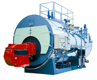
Steam Boiler
Steam Boiler
Steam boiler or simply a boiler is basically a closed vessel into which water is heated until the water is converted into steam at required pressure. This is most basic definition of boiler.

Working Principle of Boiler

The basic working principle of boiler is very very simple and easy to understand. The boiler is essentially a closed vessel inside which water is stored. Fuel (generally coal) is burnt in a furnace and hot gasses are produced. These hot gasses come in contact with water vessel where the heat of these hot gases transfer to the water and consequently steam is produced in the boiler.
Then this steam is piped to the turbine of thermal power plant. There are many different types of boiler utilized for different purposes like running a production unit, sanitizing some area, sterilizing equipment, to warm up the surroundings etc.

Steam Boiler Efficiency

The percentage of total heat exported by outlet steam in the total heat supplied by the fuel (coal) is called steam boiler efficiency.

Steam Boiler Efficiency

It includes with thermal efficiency, combustion efficiency and fuel to steam efficiency. Steam boiler efficiency depends upon the size of boiler used. A typical efficiency of steam boiler is 80% to 88%. Actually there are some losses occur like incomplete combustion, radiating loss occurs from steam boiler surrounding wall, defective combustion gas etc. Hence, efficiency of steam boiler gives this result.

Types of Boiler

There are mainly two types of boiler – water tube boiler and fire tube boiler.
  • In fire tube boiler, there are numbers of tubes through which hot gases are passed and water surrounds these tubes.
  • Water tube boiler is reverse of the fire tube boiler. In water tube boiler the water is heated inside tubes and hot gasses surround these tubes.
These are the main two types of boiler but each of the types can be sub divided into many which we will discuss later.

Fire Tube Boiler

As it indicated from the name, the fire tube boiler consists of numbers of tubes through which hot gasses are passed. These hot gas tubes are immersed into water, in a closed vessel. Actually in fire tube boiler one closed vessel or shell contains water, through which hot tubes are passed. These fire tubes or hot gas tubes heated up the water and convert the water into steam and the steam remains in same vessel. As the water and steam both are in same vessel a fire tube boiler cannot produce steam at very high pressure. Generally it can produce maximum 17.5 kg/cm2 and with a capacity of 9 Metric Ton of steam per hour.
Fire Tube Boiler
Fire Tube Boiler

Types of Fire Tube Boiler
There are different types of fire tube boiler likewise, external furnace and internal furnace fire tube boiler.

External furnace boiler can be again categorized into three different types-
  1. Horizontal Return Tubular Boiler.
  2. Short Fire Box Boiler.
  3. Compact Boiler.
Internal furnace fire tube boiler has also two main categories such as horizontal tubular and vertical tubular fire tube boiler.

Normally horizontal return fire tube boiler is used in thermal power plant of low capacity. It consists of a horizontal drum into which there are numbers of horizontal tubes. These tubes are submerged in water. The fuel (normally coal) burnt below these horizontal drum and the combustible gasses move to the rear from where they enter into fire tubes and travel towards the front into the smoke box. During this travel of gasses in tubes, they transfer their heat into the water and steam bubbles come up. As steam is produced, the pressure of the boiler developed, in that closed vessel.

Advantages of Fire Tube Boiler
  • It is quite compact in construction.
  • Fluctuation of steam demand can be met easily.
  • It is also quite cheap.
Disadvantages of Fire Tube Boiler
  • As the water required for operation of the boiler is quite large, it requires long time for rising steam at desired pressure.
  • As the water and steam are in same vessel the very high pressure of steam is not possible.
  • The steam received from fire tube boiler is not very dry.

Water Tube Boiler

A water tube boiler is such kind of boiler where the water is heated inside tubes and the hot gasses surround them. This is the basic definition of water tube boiler. Actually this boiler is just opposite of fire tube boiler where hot gasses are passed through tubes which are surrounded by water.
Water Tube Boiler
Water Tube Boiler

Types of Water Tube Boiler
There are many types of water tube boilers, such as
  1. Horizontal Straight Tube Boiler.
  2. Bent Tube Boiler.
  3. Cyclone Fired Boiler.
Horizontal Straight Tube Boiler again can be sub-divided into two different types as below:
  • Longitudinal Drum Water Tube Boiler.
  • Cross Drum Water Tube Boiler.
Bent Tube Boiler also can be sub divided into four different types as below:
  • Two Drum Bent Tube Boiler.
  • Three Drum Bent Tube Boiler.
  • Low Head Three Drum Bent Tube Boiler.
  • Four Drum Bent Tube Boiler.
Advantages of Water Tube Boiler
There are many advantages of water tube boiler due to which these types of boiler are essentially used in large thermal power plant.
  • Larger heating surface can be achieved by using more numbers of water tubes.
  • Due to convectional flow, movement of water is much faster than that of fire tube boiler, hence rate of heat transfer is high which results into higher efficiency.
  • Very high pressure in order of 140 kg/cm2 can be obtained smoothly.
Disadvantages of Water Tube Boiler
  • The main disadvantage of water tube boiler is that it is not compact in construction.
  • Its cost is not cheap.
  • Size is a difficulty for transportation and construction.

Explore Engineering Animations

  • BoilerBoiler
  • Water Tube BoilerWater Tube Boiler
  • Gas TurbineGas Turbine
  • Centrifugal CompressorCentrifugal Compressor
  • Steam TrapSteam Trap
  • Cooling TowerCooling Tower